From the pin-side:
| Pin | Description | Connects to | My Mapping Choices |
| 1 | INTRUDER 3 | INTRUDER 3, FNT 32 | |
| 2 | VCC +5v | FNT 3, FNT 4 (USB red1, red2) | Motherboard USB Header - Pin 1 |
| 3 | VCC +5v | FNT 2, FNT 4 (USB red1, red2) | Motherboard USB Header - Pin 2 |
| 4 | VCC +5v | FNT 2, FNT 3 (USB red1, red2) | |
| 5 | LED VCC | CTRL 6 thru R19, CTRL14 thru R20 | |
| 6 | ? | ||
| 7 | ? | ||
| 8 | INTRUDER 5 | INTRUDER 5 | |
| 9 | GND | GND (USB black1, black2, shield) | Motherboard USB Header - Pin 7 |
| 10 | GND? | GND? | |
| 11 | GND | GND (USB black1, black2, shield) | Motherboard USB Header - Pin 8 |
| 12 | USB2 - | (USB white2) | Motherboard USB Header - Pin 4 |
| 13 | USB2 + | (USB green2) | Motherboard USB Header - Pin 6 |
| 14 | GND | GND (USB black1, black2, shield) | |
| 15 | VCC +5v | FNT 2, FNT 3 (USB red1, red2) | |
| 16 | GND | GND (USB black1, black2, shield) | |
| 17 | USB1 - | (USB white1) | Motherboard USB Header - Pin 3 |
| 18 | USB1 + | (USB green1) | Motherboard USB Header - Pin 5 |
| 19 | GND | GND (USB black1, black2, shield) | |
| 20 | PWR SWITCH LEFT SIDE (Both) | CTRL 2 | |
| 21 | Pin removed | | |
| 22 | HDD LED NEG | CTRL 4 | |
| 23 | PWR LED GREEN POS | CTRL 5 | |
| 24 | ESUP LED NEG | CTRL 13 | |
| 25 | GND | GND (USB black1, black2, shield) | |
| 26 | ? | ||
| 27 | PWR LED YELLOW POS | CTRL 9 | |
| 28 | ESUP SWITCH RIGHT SIDE (Both) | CTRL 8 | |
| 29 | GND | GND (USB black1, black2, shield) | S-GND: Motherboard USB Header - Pin 10 |
| 30 | INTRUDER 1 | INTRUDER 1 | |
| 31 | EXT_SPK 2 | EXT_SPK 2 | |
| 32 | INTRUDER 3 | INTRUDER 3 | |
| 33 | EXT_SPK 4 | EXT_SPK 4 | |
| 34 | EXT_SPK 1 | EXT_SPK 1 |
Motherboard USB Header Pinout (http://www.frontx.com/cpx108_2.html)
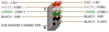
Wiring Diagram for USB